Page History: Really Simple Zero Crossing Detect
Compare Page Revisions
Page Revision: 2018/01/22 12:47
!!! WARNING, THIS ARTCLE DEALS WITH POTENTIALLY LETHAL VOLTAGES !!!If you don't feel confident in doing this, best avoid trying unless you have a low power AC source (a transformer, signal generator etc...). You will need to lower the value of the input resistor accordingly to give about 2 to 2.5mA (R=V/I).
Zero crossing detect circuits are used to indicate the point at which an AC signal swings from positive to negative (and vice versa) passing through its zero volt point (or within a few volts of it).
This might be to allow the switching of current or audio at a nice place to prevent interference or surges etc. These are my thoughts on a really simple ZCD circuit which I got down to three components!
Remember Mains AC is usually stated as
RMS (RMS is the equivalent DC voltage required to do the same work). This means you need to divide by 0.707 (square root of 2 divided by 2) to get the peak voltage you can expect on the input.

In the UK, mains is 240V RMS / 0.707 = 339V peak (50Hz).
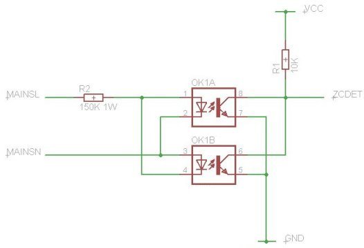
The circuit below works by illuminating the two LEDs in an optocoupler alternately. They need anything from about 1.8V upwards to start glowing. Once on, they force the transistors to drag the ZCDET output LO - which is for the majority of the half cycle. The practical up-shot of this is that when the LEDs are dark (the voltage at the input is between +1.8V and -1.8V) the ZCDET output goes HI, indicating the voltage at the input is (effectively) at zero and the AC voltage is passing through its zero volt point on the way to another half-cycle. Each LED is protected from high reverse voltage by its counterpart.
The input resistor is 150KΩ which (339/150000) gives about 2.2mA, but (339*0.0022) 0.77W peak power dissipation! It won't, in reality, be that high because we are not constantly at that voltage but be aware of these limitations - it is probably a good idea to over-design the circuit. For long term use you should be looking at a 1W resistor here - I didn't have a 150KΩ at 1W so for the sake of testing for a few minutes I used a 0.5W resistor. It does get noticeably warm during 10 minutes of use at 240V -
DON'T STICK YOUR FINGER ON THIS TO CHECK THE HEAT WITH THE POWER ON!!!For the later tests I operated this with 20V P-P and it was good to 1KHz... the pulses tend to flatten out a lot above that. The edges on the pulse are fairly slow so I wouldn't recommend driving a MOSFET directly from this pulse (they get hot if not switched quickly). If you want faster edges on your pulse, you could feed the output into the base of a signal transistor forming a Darlington pair with the two in the opto-coupler. This transistor would "saturate" at about 0.6V which would sharpen the edge and make it much more responsive to the changing voltage - I haven't tried this though as I was more interested in getting a tiny component count. The best pulse shaping would be achieved with a Schmitt trigger device, something like a 74HC14 or straight into a Schmitt input on a micro-controller.
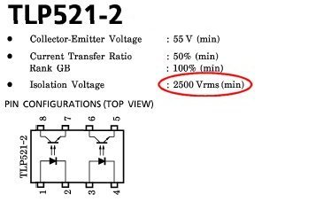
If you are messing with high voltages, you want to protect your delicates... Choose an optocoupler with good isolation (the minimum voltage required to jump from the LEDs to the transistors). The TLP521 range is ten times higher than normal UK mains.
Here's the crazy simple schematic:
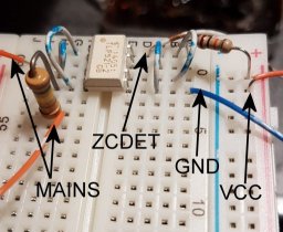
and here is my quick knock-up on a breadboard
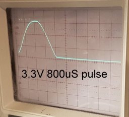
This produces a nice pulse of 800uS (Vcc=3.3v) and 1mS (Vcc=5v) - not exactly square but definitely good enough to be seen and not a terribly slow rise time -gets to 1v in 100uS. Even a 4MHz microcontroller shouldn't have too much trouble polling for the top 400uS of the pulse, you probably wouldn't need to "waste" an interrupt on it.
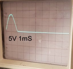
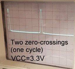
And here is a photo of the AC waveform and pulses added together (I had to do it like this because my camera exposure was too quick and wouldn't capture both traces).
The positive going edges of the pulses seem to occur around the +/-2v mark - which is to be expected from LEDs.
