Page History: Capacitive Dropper Calculator for Current and Capacitance
Compare Page Revisions
Page Revision: 2021/10/25 07:38
Often times you need a small amount of power derived from a mains source - perhaps just a few tens of milli-amps to drive a micro-controller. In such cases, it can be difficult to justify the expense and size of a switched mode PSU module let alone a transformer-based linear PSU. Very often, a resistor is used to reduce voltages to working levels, but with mains, there is a lot to "shave off" and resistors are quite inefficient for such an application. Simply "burning off" the excess, they generate a lot of heat which needs to be vented and this leads to large bulky resistors... back to square one.
A better way (with caveats - we will approach in a moment) is to use a
capacitive dropper circuit - that link provides all the information you could want to understand & design such a circuit. It uses the phenomenon of reactance of a capacitor to pass only a portion of the available power, so it looks a bit like a resistor to the supply but you get none of the downsides of actually using a resistor. When deriving power from mains in this manner the capacitor needs to be rated at 400V (Peak mains in UK can be 350V) and it should be "
X" type for safety.
A few years back I had a need to provide a great many lighting controllers that fitted inside a ceiling rose and controlled the light on the pendant below. A PSU module would have added considerably to the project cost ignoring the confines of the ceiling rose. A capacitive dropper was designed on the controller board, fitting perfectly in the space available and provided the 75mA required.
CaveatsBefore you rush off thinking capacitive droppers are a miracle answer to small mains powered PSUs, you should consider the following. They are often viewed with disdain or at least a sideways glance and a disapproving "hmmmmm" from electronics engineers, but done properly (and that means safely, clearly marked and using something else if you can) and treated with respect they are fine, but:
- a. It is vital to get the mains Live and Neutral connections the right ways round to avoid the very serious, possibly fatal, risk of electric shock. If reversed, your dropper will still work, but the 0V/GND rail will be at mains potential. If someone innocently touches or attaches something to 0V (which is usually fine) and then bridges to an earth connection - the full mains potential is now routed through them. Don't leave it to chance: use a DMM to check the voltage between Earth and the Live & Neutral wires. From Earth to Live, you should see a healthy 100 - 260V (depending where in the world you are. 260 volts (or even higher) is common in UK in areas with solar panels feeding into the mains - no voltage drop, no current flow. The electricity generators have a real problem with grid voltage because of solar feed-in, but that is another story). From Earth to Neutral you should see only a very small voltage - hopefully a lot less than 10 volts (it should be zero but perfect neutrals are rare). If you are confused by what you see - get an electrician in to check everything out - DON'T TAKE RISKS!
- b. There is no Galvanic isolation of the circuit (there is a current path all the way back to the mains). The 0V/GND rail is effectively connected to the mains Neutral, but this is not in itself an issue in a properly functioning mains electrical system (see above). Attaching any mains powered equipment (i.e. the ground connection of an oscilloscope lead) to the DC side of such a circuit will probably trip the RCD at the consumer board. This is because a tiny amount of current will leak out through the 'scope ground/earth (instead of all the return flow going via the circuit's neutral connection). E.g. the RCD may "see" 70mA going into your dropper's Live but only 60mA coming back out of its Neutral. The imbalance of current will cause the RCD to trip the mains power to minimise any perceived injury (in fact, if it didn't, I would investigate that RCD as potentially faulty). To attach equipment on the DC side, it must be either, battery powered or through an isolation transformer. It is more common to power the dropper via such a transformer while under test. This does not apply to battery powered devices e.g. a DMM.
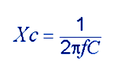
The calculation behind all this is fairly simple, based on the electrical principles staple for reactance(X) of a capacitor(c);

Below is a tiddly trinket (I used MMBasic but it is simple enough to transcribe into just about any language) to take the required values and quickly determine either the current you can get from a dropper circuit based on the value of its capacitor or the capacitance required to supply a given current. It isn't rocket-science but it takes the grunt out of one more chore.
The Code
Dim Float C,V,F,A,x
Dim y$
'defaults, change them if you need to
V=240
F=50
Print "***************************************************"
Print "* Capacitive dropper Current/Capacitor calculator *"
Print "***************************************************"
Do
Print: Print "Which do you wish to calculate:"
Print "The Current available in a circuit[A]"
Print "or"
Print "The Capacitance required to deliver a given current[C]"
Input y$
y$=Ucase$(y$)
Loop Until y$="A" or y$="C"
Print "Enter Supply Voltage (Vrms): [";V;"] >";
Input"", x
If x Then V=x
Print "Enter Supply Frequency (Hz): [";F;"] >";
Input"", x
If x Then F=x
If y$="A" Then
Input "Enter Capacitor Value (nF): ",C
c=c/1e9' coz nF
A=2*Pi*C*V*F*1000
Print "Available Current is : ";STR$(A, 1, 5);"mA"
Else
Input "Enter Desired Current (mA): ",A
a=a/1e3' coz mA
C=(1/(2*Pi*V*F))*A*1e9
Print "Required Capacitance is : ";Str$(C,1,3);"nF"
EndIf
worked examples:{{
> RUN
FORMATTER ERROR (Malformed List){{
> RUN
FORMATTER ERROR (Malformed List)